Unlocking Voltage Simplicity: How the Voltage Divider Formula Powers Precision Potentiometry
Unlocking Voltage Simplicity: How the Voltage Divider Formula Powers Precision Potentiometry
For engineers, DIY hobbyists, and electronic designers, controlling voltage precisely is not just a technical requirement—it’s a foundation for reliable performance. The voltage divider, based on a deceptively simple yet profound formula, stands as the cornerstone of voltage regulation in countless circuits. Far from a relic of analog circuitry, this principle underpins modern electronics, enabling everything from sensor calibration to precision signal conditioning.
By mastering the voltage divider formula, users gain the ability to subtract voltage ratios with mathematical certainty, turning theoretical design into practical reality.
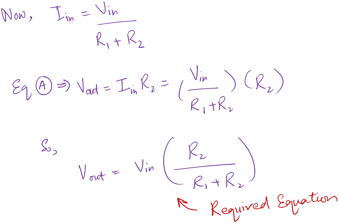
At the heart of voltage division lies a core equation that belies its transformative impact: Vout = Vin × (R2 / (R1 + R2). This formula describes how a fraction of an input voltage emerges across a resistor (R2) in series with another resistor (R1). Its elegance stems from straightforward ratios—when R2 is held constant, increasing R1 reduces the output voltage, and vice versa.
But beneath this simplicity lies a world of precision and calibration.
The Mathematics of Voltage Division: Precision Through Ratios
The voltage divider formula, Vout = Vin × (R2 / (R1 + R2), is rooted in fundamental principles of parallel and series resistance. In a series configuration, total resistance Rtotal = R1 + R2, and current I flows uniformly through both resistors. By Ohm’s Law (V = IR), the voltage drop across R2—Vout—scales directly with its resistance relative to the sum.
This ratio-based relationship ensures predictable, repeatable output, essential for applications demanding exact voltage levels.
For example, consider a 12V input fed into a voltage divider with R1 = 9kΩ and R2 = 3kΩ. Calculating, Vout = 12 × (3 kΩ / (9 kΩ + 3 kΩ)) = 12 × (1/3) = 4V. The formula demystifies how even uneven resistor ratios produce precise divisions—critical when calibrating instrumentation or powering low-voltage CMOS circuits.
Applications Across Industries: From Sensors to Consumer Electronics
The voltage divider’s reach extends far beyond textbook diagrams.
In sensor interfaces, for instance, potentiometers act as analog voltmeters: movement adjusts R2, shifting Vout to signal physical parameters like light intensity or temperature. In medical devices, precise voltage references ensure diagnostic accuracy; in automotive systems, voltage dividers enable memory backup circuits and sensor telemetry.
Beyond precision measurement, this formula underpins battery voltage monitoring. A 9V battery’s output sag under load can be tracked by measuring Vout across a faulted series resistor—exposing wear before failure.
In consumer tech, from audio volume controls to LED dimming circuits, voltage dividers deliver intuitive, tactile adjustment. The formula’s simplicity allows engineers to design responsive, user-friendly interfaces grounded in predictable physics.
Design Considerations: Balance, Tolerance, and Real-World Factors
Successful implementation requires more than applying the voltage divider formula—it demands careful resistor selection and environmental awareness. Resistor tolerances (typically ±1% to ±5%) impact precision; a 5% resistor introduces a ±5% Vout deviation under nominals, demanding tighter sourcing for high-accuracy designs.
Thermal effects further complicate matters: resistances drift with temperature, potentially shifting Vout by tens of millivolts. For stability, low-temp-coefficient 0.1% or 1% metal-film resistors are preferred in calibrated circuits.
PCB layout also plays a role. Parasitic capacitance and trace resistance can distort small-signal dividers, necessitating guarding or shielding.
In precision labs, expert heat sinking and current-limiting resistors prevent self-heating that degrades divisor performance. Proper termination—using matched, low-noise connections—ensures Vout faithfully reflects input voltage, free from noise or dropout.
Challenges and Mitigations in Practical Design
Despite its robustness, voltage dividers face practical hurdles. Loading effects arise when loads draw significant current through R2, altering its effective resistance and distorting Vout.
To counter this, buffer amplifiers or current-buffered dividers isolate the load, preserving voltage fidelity. Similarly, supply voltage fluctuations can destabilize the output; integrating a voltage reference prior to the divider, or using feedback in active circuits, stabilizes Vin and enhances reliability.
In digital age circuits, passive dividers sometimes give way to active alternatives—op-amp voltage followers—that regenerate clean signals. Yet the passive divider, based on its core formula, remains indispensable for analog precision.
Its elegant simplicity ensures it endures where stability and accessibility converge.
Real-World Example: Sensing with Potentiometers
Consider a light-controlled lamp using a variable potentiometer. As ambient light shifts, the potentiometer’s entire resistive path varies: at night, R2 decreases,


Related Post

Quiero Água Gore: The Rising Trend In Water Consumption
Prince Philips Beard A Royal Style Icon: The Cultural Power Behind a Grooming Legend

Send To Kindle: Mastering Seamless E-book Distribution in Minutes

Navy Federal Max ATM Withdrawal: Unlocking Tap-Directed Access with Navy Federal’s Secure Cash Eruption