Mastering Circuit Integrity: How to Measure Continuity with a Multimeter
Mastering Circuit Integrity: How to Measure Continuity with a Multimeter
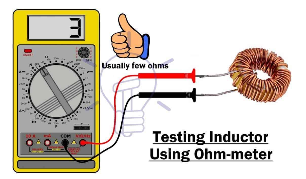
Ensuring uninterrupted electrical flow is fundamental to safe and reliable performance in electronics, automotive systems, and industrial installations. Continuity—a measure of a complete, low-resistance path for current—serves as a cornerstone diagnostic test. Using a multimeter to measure continuity is a precise, accessible method that offers instant feedback, empowering technicians, DIY enthusiasts, and engineers alike to verify circuit integrity. This protocol eliminates guesswork, identifies open circuits and faulty wiring, and prevents costly repairs fueled by undetected breaks. Mastery of this technique transforms troubleshooting from a challenge into a systematic practice rooted in measurement and verification. Continuity refers to the unbroken flow of electric current through a closed conductive path. At its core, continuity exists when electrons encounter no resistance—such as in a solid wire—allowing full circuit completion. A closed circuit, often denoted as “continuous,” permits measurable current flow; a broken connection, or open circuit, results in zero or negligible current. While multimeters cannot detect voltage, they excel at identifying continuity by testing for zero resistance across a sequence of points. “In essence, continuity checks confirm whether current can move freely from one node to another without interruption,” explains electrical engineer Dr. Lena Torres. “This insight is vital for validating wiring integrity, Especially under dynamic conditions like startup or load changes.” To measure continuity effectively, understanding the multimeter modes and proper test procedures is essential. Most digital multimeters (DMMs) include a dedicated continuity mode—often represented by a soundwave symbol or the word “CONTINUITY”—designed to emit a beep when a closed path is detected. Analog models may use resistance measurement, but DMMs in continuity mode simplify the process. The key insight: continuity measurement cannot quantify resistance—only whether it approaches zero (typically under 50 ohms, depending on the device). For robust diagnostics, at least three points (node A to node B, then node B to node C, etc.) should be tested to detect partial breaks or hidden loose connections. Before initiating a continuity test, meticulous preparation is non-negic. First, power down and disconnect the circuit to eliminate risk of electric shock or false readings. If working with wiring, locate the segment suspected of disruption— Hörnlein points to common failure zones like bent terminals, corroded connectors, or frayed insulation.
Avoid touching screws or metal frames directly—focus on wire interiors or connection points.
Interpreting results demands precision. A steady, unbroken beep indicates full conductivity—ideal for confirmed good wiring.
A suppressed or interrupted tone reveals an open path, signaling a break between two points. However, reading 0.1–99 ohms (particularly in high-resistance environments) does not confirm continuity but only suggests partial closure—often due to corrosion or loose contact. Dr.
Torres stresses, “Always treat resistance readings under 50 ohms as functional continuity, but never rely solely on resistance testing for critical breaks.”
Advanced troubleshooting includes sequential testing. For example, tracing a faulty switch might involve three steps: 1. Measure continuity across terminals under normal operation.
2. Isolate segments by testing between known good points. 3.
Forward-probe from connectors inward to pinpoint exact failure (e.g., cracked solder joint).
Wiring systems exhibit unique quirks that demand nuanced attention. In automotive circuits, continuity checks frequently uncover intermittent faults like chafed ground straps or failing relays masked by stable resistance. Similarly, in home electrical panels, continuity tests expose hidden fractures behind sealed junction boxes.
Multi-segment circuits benefit from dividing the path into discrete segments, improving diagnostic accuracy. As portable electronics age, continuity testing identifies worn battery contacts before total failure—informing timely replacements before downtime.
The practical value of this method extends beyond diagnostics. Technicians report reduced trial-and-error time by 40–60% when integrating continuity checks into routine maintenance.
Whether in industrial motor systems, telecommunications backbone circuits, or repair workshops, measuring continuity transforms abstract reliability into measurable reality—empowering informed action grounded in data. “Continuity isn’t just a snapshot—it’s a predictive tool,” says field engineer Raj Patel. “Once you identify a break, you’ve prevented potential accidents, material waste, and delays—turning preventive maintenance into a proactive discipline.”
To summarize, measuring continuity using a multimeter is a powerful, reliable technique grounded in fundamental electrical principles.
By isolating path integrity through precise probing and interpreting results within context, technicians unlock the ability to detect, diagnose, and resolve breaks before they escalate. This disciplined approach ensures circuits operate as intended, safeguarding equipment, people, and systems alike.


Related Post

Cleen Rock One And Megan The Ultimate Guide To Clean For Your Wife: A Professional, Practical Blueprint

From Threads to Triumph: The Powerful Rise of Andrew Shingange, Hyunjung Kim, and Ten Kim Threads

Dogas Info Game Your Ultimate Guide: Unlocking the Secrets of Dog Training with Play, Data, and Strategy

Ultimate Breakdown of Bount Arc Episodes: The Climactic Journey of Unity and Rebellion


